The 812H/V70D Homebrew Push-Pull Rig
|
|
|
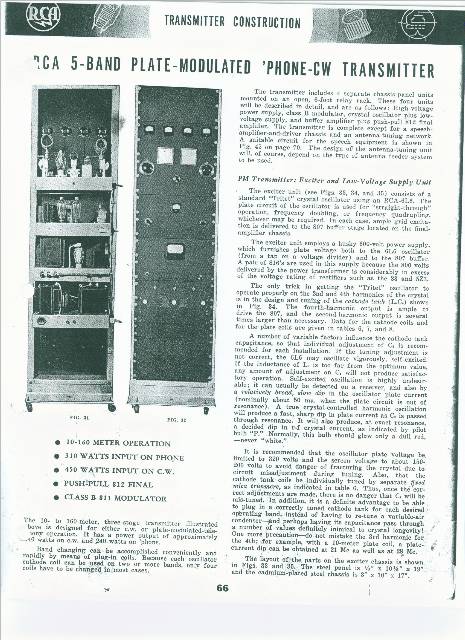
This rig is a classic pre/post WWII transmitter based upon the popular RCA 812 and 811 triodes that were introduced in the late 1930's. This particular rig was patterned almost totally after a design found in the 1941 printing of the "RCA Guide for Transmitting Tubes" handbook. The title of the article was "A 5-Band Plate Modulated phone-CW Transmitter" It is estimated to have been built shortly after the war.
I located this transmitter through a vintage gear web site (NOT Ebay) in 1998. It was located in northern Rhode Island and being sold by another ham. It had belonged to a dentist and it was in the possession of his son who needed to clean out the house. The story goes that the dentist had the transmitter built for him - I am not sure if that was the case, but the builder (whoever he was) did an excellent job of construction and high quality parts were used throughout.
The rig uses a 6L6 Tri-tet oscilator, 807 buffer amp, and the 812 type class C finals. The speech amp/driver is a 6SJ7 amp and a 6N7 phase inverter driving a pair of 2A3's. The modulators are 811A's or the 7.5 volt filament 5514's that I am using now. The LV rectifiers are 816's and a 5U4, and the HV rectifiers are 3B28's.
After studying the photos that the seller sent me and reading the RCA article, I couldn't resist and decided to take the plunge and drive up to rescue it.
When I arrived, the transmitter had been moved and was totally dismantled, making it difficult to determine if it was all there. It didn't look quite as nice as it did in the photos, in fact, my first reaction was to cut my loses, leave it there and go home. Most of the plug in coils were badly deteriorated, there was wax dripping from some of the transformers, a lot of the insulation on the wiring had dried out and was flaking off, there were broken HV connectors, it really was pretty rough. I knew it was going to take a lot of time and effort to restore it back to proper operating order and to make it look good once again. I decided it would make a good challenge, so I went ahead and loaded it up, paid the fellow and, after a good nights sleep, made the 550 mile return trip home.
It was already October and I knew there was a lot of outside work to be done, so I wasted no time in getting started. The decks and cabinet were encrusted with decades of dirt so I stripped each deck of its components and scrubbed them down. The parts that were candidates for the dishwasher went there for a good cleaning. Deck by deck I repeated this process until all 5 chassis's were reassembled. Now it was time to clean and repaint the Bud cabinet with a light over-spray of matte black paint to retain that "old buzzard" black wrinkle look. The first flakes of snow were already beginning to fly when I got the last of the transmitter down in the basement to begin the long process of bringing it back to life - deck by deck.
 |
 |
 |
 |
|
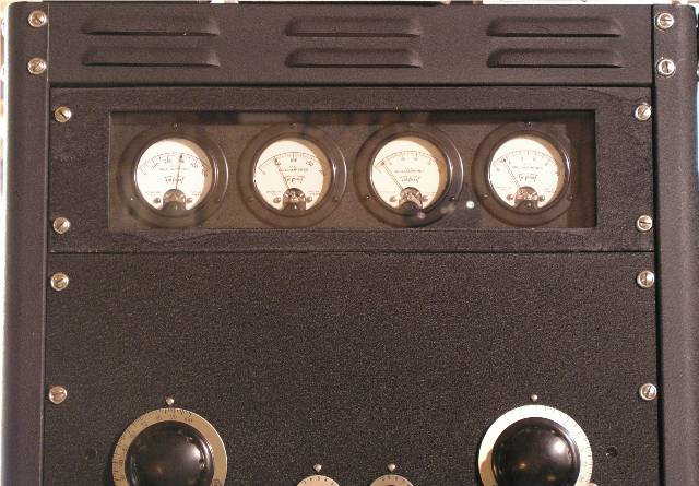 |
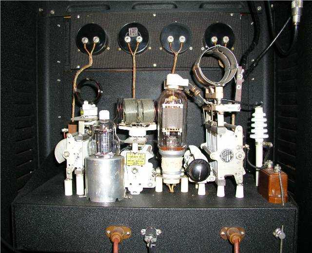
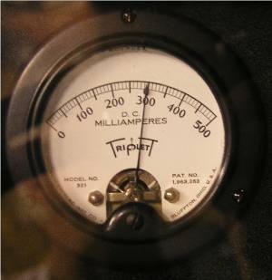
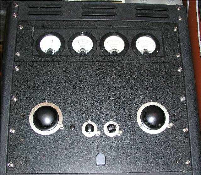
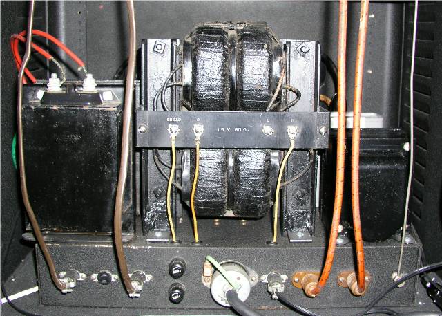
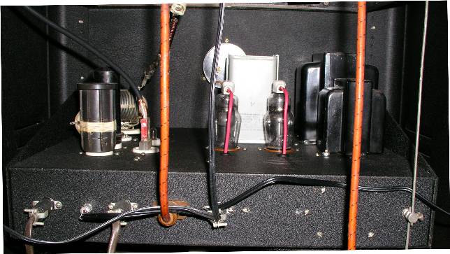
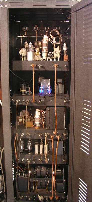
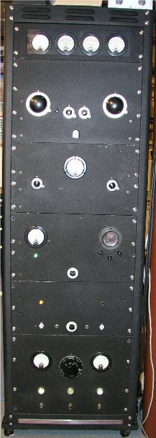
| HV Power Supply Deck with "old buzzard" open frame xfmr | 2A3 Speech Amp Deck with 6N7 phase inverter | Modulator Deck 811A's or 5514's | 6L6 oscillator & LV PS Deck using 816 rectifiers | Class C PP Final 812H's or V70D's | Recessed Meter
Panel
|
After the initial cleaning I felt much better about the future of this transmitter. Deck by deck, it came back to life. I was able to power each deck up separately and take care of the obvious problems right away. I had to either rebuild or replace all of the plug-in coils. There was a bad filament transformer. The class B driver transformer was toast - I really hated that as it was a classic black wrinkle Thordarson unit that matched the modulation xfmr. The Derb - N3DRB gave me a suitable replacement and that was the worst of the bad component issues. I replaced all of the caps and questionable resistors.
The rig made it's maiden voyage in February of 1999 on 75 meters. I have constantly been making improvements to it ever since. I originally used a Heath-kit VF-1 but am now using the stations Fluke generator at 1.5 volts. The control circuits were totally redesigned and I added a variable series capacitor after the swinging link. It was "in the open" on top of the rig but it is now enclosed in a metal box on the top left side the of rig to lessen RF in the shack.
 |
 |
 |
 |
 |
 |
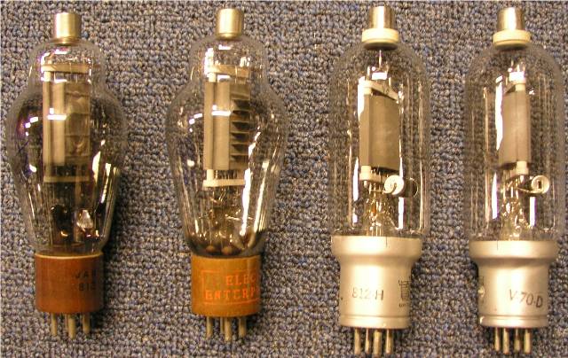
I can pretty much interchangeably use either 812's, 812A's, 812H's, or V70D's in this rig with only slight neutralization and filament voltage changes. Shown below in that order.